Once the top-down design approach is taken, the modular approach is useful in programming. This approach involves breaking the programming into logical, manageable portions, or modules. This kind of programming works well with top-down design because it emphasizes the interfaces between modules and does not neglect them until later in systems development. Ideally, each individual module should be functionally cohesive so that it is charged with accomplishing only one function.
Modular program design has three main advantages. First, modules are easier to write and debug because they are virtually self-contained. Tracing an error in a module is less complicated, because a problem in one module should not cause problems in others.
A second advantage of modular design is that modules are easier to maintain. Modifications usually will be limited to a few modules and will not be spread over an entire program. A third advantage of modular design is that modules are easier to grasp, because they are self contained subsystems. Hence, a reader can pick up a code listing of a module and understand its function.
Some guidelines for modular programming include the following:
- Keep each module to a manageable size (ideally including only one function).
- Pay particular attention to the critical interfaces (the data and control variables that are passed to other modules).
- Minimize the number of modules the user must modify when making changes.
- Maintain the hierarchical relationships set up in the top-down phases.
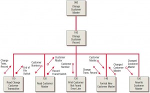
The recommended tool for designing a modular, top-down system is called a structure chart. A structure chart is simply a diagram consisting of rectangular boxes, which represent the modules, and connecting arrows.
Figure illustrated below is a set of modules used to change a customer record, shows seven modules that are labeled 000, 100, 110, 120, and so on. Higher-level modules are numbered by 100s, and lower-level modules are numbered by 10s. This numbering allows programmers to insert modules using a number between the adjacent module numbers. For example, a module inserted between modules 110 and 120 would receive number 115.

Off to the sides of the connecting lines, two types of arrows are drawn. The arrows with the empty circles are called data couples, and the arrows with the filled-in circles are called control flags or switches. A switch is the same as a control flag except that it is limited to two values: either yes or no. These arrows indicate that something is passed either down to the lower module or up to the upper one.
Ideally, the analyst should keep this coupling to a minimum. The fewer data couples and control flags one has in the system, the easier it is to change the system. When these modules are actually programmed, it is important to pass the least number of data couples between modules.
Even more important is that numerous control flags should be avoided. Control is designed to be passed from lower-level modules to those higher in the structure. On rare occasions, however, it will be necessary to pass control downward in the structure. When control is passed downward, a low-level module is allowed to make a decision, and the result is a module that performs two different tasks. This result violates the ideal of a functional module: It should perform only one task.
Even when a structure chart accomplishes all the purposes for which it was drawn, the structure chart cannot stand alone as the sole design and documentation technique. First, it doesn’t show the order in which the modules should be executed (a data flow diagram will accomplish that). Second, it doesn’t show enough detail (Structured English will accomplish that).
