PERT is an acronym for Program Evaluation and Review Techniques. A program (a synonym for a project) is represented by a network of nodes and arrows that are then evaluated to determine the critical activities, improve the schedule if necessary, and review progress once the project is undertaken. PERT was developed in the late 1950s for use in the U.S. Navy’s Polaris nuclear submarine project. It reportedly saved the U.S. Navy two years’ development time.
PERT is useful when activities can be done in parallel rather than in sequence. The systems analyst can benefit from PERT by applying it to systems projects on a smaller scale, especially when some team members can be working on certain activities at the same time that fellow members are working on other tasks.
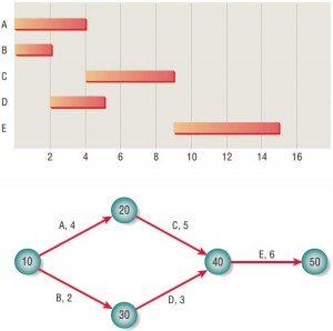
Figure 1 compares a simple Gantt chart with a PERT diagram. The activities expressed as bars in the Gantt chart are represented by arrows in the PERT diagram. The length of the arrows has no direct relationship with the activity durations. Circles on the PERT diagram are called events and can be identified by numbers, letters, or any other arbitrary form of designation. The circular nodes are present to (1) recognize that an activity is completed and (2) indicate which activities need to be completed before a new activity may be undertaken (precedence).

In reality activity C may not be started until activity A is completed. Precedence is not indicated at all in the Gantt chart, so it is not possible to tell whether activity C is scheduled to start on day 4 on purpose or by coincidence.
A project has a beginning, a middle, and an end; the beginning is event 10 and the end is event 50. To find the length of the project, each path from beginning to end is identified, and the length of each path is calculated. In this example path 10–20–40–50 has a length of 15 days, whereas path 10–30–40–50 has a length of 11 days. Even though one person may be working on path 10–20–40–50 and another on path 10–30–40–50, the project is not a race. The project requires that both sets of activities (or paths) be completed; consequently, the project takes 15 days to complete.
The longest path is referred to as the critical path. Although the critical path is determined by calculating the longest path, it is defined as the path that will cause the whole project to fall behind if even one day’s delay is encountered on it. Note that if you are delayed one day on path 10–20–40–50, the entire project will take longer, but if you are delayed one day on path 10–30–40–50, the entire project will not suffer. The leeway to fall behind somewhat on noncritical paths is called slack time.
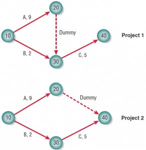
Occasionally, PERT diagrams need pseudo-activities, referred to as dummy activities, to preserve the logic of or clarify the diagram. Figure 3.20 shows two PERT diagrams with dummies. Project 1 and project 2 are quite different, and the way the dummy is drawn makes the difference clear. In project 1 activity C can only be started if both A and B are finished, because all arrows coming into a node must be completed before leaving the node. In project 2, however, activity C requires only activity B’s completion and can therefore be under way while activity A is still taking place.

Project 1 takes 14 days to complete, whereas project 2 takes only 9 days. The dummy in project 1 is necessary, of course, because it indicates a crucial precedence relationship. The dummy in project 2, on the other hand, is not required, and activity A could have been drawn from 10 to 40 and event 20 may be eliminated completely.
Therefore, there are many reasons for using a PERT diagram over a Gantt chart. The PERT diagram allows:
- Easy identification of the order of precedence.
- Easy identification of the critical path and thus critical activities.
- Easy determination of slack time.
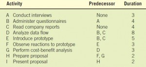
A PERT EXAMPLE. Suppose a systems analyst is trying to set up a realistic schedule for the data gathering and proposal phases of the systems analysis and design life cycle. The systems analyst looks over the situation and lists activities that need to be accomplished along the way. This list, which appears in Figure 3, also shows that some activities must precede other activities. The time estimates were determined as discussed in an earlier section of this chapter.

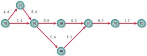
DRAWING THE PERT DIAGRAM. In constructing the PERT diagram, the analyst looks first at those activities requiring no predecessor activities, in this case A (conduct interviews) and C (read company reports). In the example in Figure 4, the analyst chose to number the nodes 10, 20, 30, and so on, and he or she drew two arrows out of the beginning node 10. These arrows represent activities A and C and are labeled as such. Nodes numbered 20 and 30 are drawn at the end of these respective arrows. The next step is to look for any activity requiring only A as a predecessor; task B (administer questionnaires) is the only one, so it can be represented by an arrow drawn from node 20 to node 30.

Because activities D (analyze data flow) and E (introduce prototype) require both activities B and C to be finished before they are started, arrows labeled D and E are drawn from node 30, the event that recognizes the completion of both B and C. This process is continued until the entire PERT diagram is completed. Notice that the entire project ends at an event called node 80.
IDENTIFYING THE CRITICAL PATH. Once the PERT diagram is drawn, it is possible to identify the critical path by calculating the sum of the activity times on each path and choosing the longest path. In this example, there are four paths: 10–20–30–50–60–70–80, 10–20–30–40–60–70–80, 10–30–50–60–70–80, and 10–30–40–60–70–80. The longest path is 10–20–30–50–60–70–80, which takes 22 days. It is essential that the systems analyst carefully monitors the activities on the critical path so as to keep the entire project on time or even shorten the project length if warranted.
Contents
- Project Initiation
- Defining the Problem in Project Initiation
- Selection of Projects
- Feasibility Study – Determining Whether the Project is Feasible
- Technical Feasibility – Ascertaining Hardware and Software Needs
- Acquisition of Computer Equipment – Technical Feasibility
- Software Evaluation in Technical Feasibility
- Economic Feasibility – Identifying & Forecasting Costs & Benefits
- Comparing Costs and Benefits – Economic Feasibilty
- Activity Planning and Control – Project Management
- Using PERT Diagrams in Project Planning
- Managing the Project
- Managing Analysis and Design Activities
- Creating the Project Charter & Avoiding Project Failures
- Organizing the Systems Proposal
- Using Figures for Effective Communication in System Proposal
