The UML approach is well worth investigating and understanding, due to its wide acceptance and usage. UML provides a standardized set of tools to document the analysis and design of a software system. The UML toolset includes diagrams that allow people to visualize the construction of an object-oriented system, similar to the way a set of blueprints allows people to visualize the construction of a building. Whether you are working independently or with a large systems development team, the documentation that you create with UML provides an effective means of communication between the development team and the business team on a project.
UML consists of things, relationships, and diagrams, as shown in the table illustration below. The first components, or primary elements, of UML are called things. You may prefer another word, such as object, but in UML they are called things. Structural things are most common. Structural things are classes, interfaces, use cases, and many other elements that provide a way to create models. Structural things allow the user to describe relationships. Behavioral things describe how things work. Examples of behavioral things are interactions and state machines. Group things are used to define boundaries. An example of a group thing is a package. Finally, we have annotational things, so that we can add notes to the diagrams.
| UML Category | UML Elements | UML Elements |
|---|---|---|
| Things | Structural Things | Classes Interfaces Collaborations Use Cases Active Classes Components Nodes |
| Behavioral Things | Interactions State Machines | |
| Grouping Things | Packages | |
| Annotational | Things Notes | |
| Relationships | Structural Relationships | Dependencies Aggregations Associations Generalizations |
| Behavioral Relationships | Communicates Includes Extends Generalizes | |
| Diagrams | Structural Diagrams | Class Diagrams Component Diagrams Deployment Diagrams |
| Behavioral Diagrams | Use Case Diagrams Sequence Diagrams Communication Diagrams Statechart Diagrams Activity Diagrams |
Relationships are the glue that holds the things together. It is useful to think of relationships in two ways. Structural relationships are used to tie the things together in the structural diagrams. Structural relationships include dependencies, aggregations, associations, and generalizations. Structural relationships show inheritance, for example. Behavioral relationships are used in the behavioral diagrams. The four basic types of behavioral relationships are communicates, includes, extends, and generalizes.
There are two main types of diagrams in UML: structural diagrams and behavioral diagrams. Structural diagrams are used, for example, to describe the relationships between classes. They include class diagrams, object diagrams, component diagrams, and deployment diagrams. Behavioral diagrams, on the other hand, can be used to describe the interaction between people (called actors in UML) and the thing we refer to as a use case, or how the actors use the system. Behavioral diagrams include use case diagrams, sequence diagrams, communication diagrams, statechart diagrams, and activity diagrams.
In the remainder of this chapter, we first discuss use case modeling, the basis for all UML techniques. Next, we look at how a use case is used to derive activities, sequences, and classes—the most commonly used UML diagrams. Because entire books are dedicated to the syntax and usage of UML (the actual UML specification document is over 800 pages long), we provide only a brief summary of the most valuable and commonly used aspects of UML.
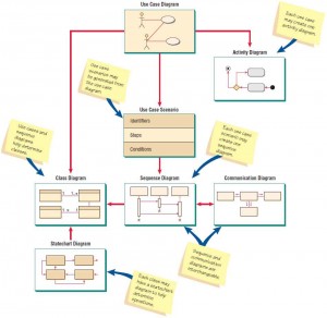
The six most commonly used UML diagrams are:
- A use case diagram, describing how the system is used. Analysts start with a use case diagram.
- A use case scenario (although technically it is not a diagram). This scenario is a verbal articulation of exceptions to the main behavior described by the primary use case.
- An activity diagram, illustrating the overall flow of activities. Each use case may create one activity diagram.
- Sequence diagrams, showing the sequence of activities and class relationships. Each use case may create one or more sequence diagrams. An alternative to a sequence diagram is a communication diagram, which contains the same information but emphasizes communication instead of timing.
- Class diagrams, showing the classes and relationships. Sequence diagrams are used (along with CRC cards) to determine classes. An offshoot of a class diagram is a gen/spec diagram (which stands for generalization/specialization).
- Statechart diagrams, showing the state transitions. Each class may create a statechart diagram, which is useful for determining class methods.
How these diagrams relate to one another is illustrated in Figure 10.5. We will discuss each of these diagrams in the following sections.

