It is important to understand how data are represented before considering the use of files or the database approach. In this section, critical definitions are covered, including the abstraction of data from the real world to the storage of data in tables and database relations.
Reality, Data, and Metadata
The real world will be referred to as reality. Data collected about people, places, or events in reality will eventually be stored in a file or database. To understand the form and structure of the data, information about the data itself is required. The information that describes data is referred to as metadata.
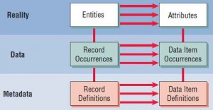
The relationship between reality, data, and metadata is pictured in the figure shown below. Within the realm of reality are entities and attributes; within the realm of actual data are record occurrences and data item occurrences; and within the realm of metadata are record definitions and data item definitions. The meanings of these terms are discussed in the following subsections.

Any object or event about which someone chooses to collect data is an entity. An entity may be a person, place, or thing (for example, a salesperson, a city, or a product). Any entity can also be an event or unit of time such as a machine breakdown, a sale, or a month or year. In addition to the entities discussed in Chapter “Understanding and Modeling Organizational Systems” is an additional minor entity called an entity subtype. Its symbol is a smaller rectangle within the entity rectangle.
An entity subtype is a special one-to-one relationship used to represent additional attributes (fields) of another entity that may not be present on every record of the first entity. Entity subtypes eliminate the situation in which an entity may have null fields stored on database tables.
An example is the primary entity of a customer. Preferred customers may have special fields containing discount information, and this information would be in an entity subtype. Another example is students who have internships. The STUDENT MASTER should not have to contain information about internships for each student, because perhaps only a small number of students have internships.
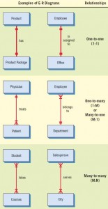
Relationships are associations between entities (sometimes they are referred to as data associations). Figure illustrated below is an entity-relationship (E-R) diagram that shows various types of relationships.

The first type of relationship is a one-to-one relationship (designated as 1:1). The diagram shows that there is only one PRODUCT PACKAGE for each PRODUCT. The second one-to-one relationship shows that each EMPLOYEE has a unique OFFICE. Notice that all these entities can be described further (a product price would not be an entity, nor would a phone extension).
Another type of relationship is a one-to-many (1:M) or a many-to-one association. As shown in the figure above, a PHYSICIAN in a health maintenance organization is assigned many PATIENTS, but a PATIENT is assigned only one PHYSICIAN. Another example shows that an EMPLOYEE is a member of only one DEPARTMENT, but each DEPARTMENT has many EMPLOYEES.
Finally, a many-to-many relationship (designated as M:N) describes the possibility that entities may have many associations in either direction. For example, a STUDENT can have many COURSE(s), and at the same time a COURSE may have many STUDENT(s) enrolled in it. The second example shows that a SALESPERSON can call on many CITY(s) and a CITY can be a sales area for many SALESPERSON(s).
The standard symbols for crow’s foot notation, the official explanation of the symbols, and what they actually mean, are all given in the illustration below. Notice that the symbol for an entity is a rectangle. An entity is defined as a class of a person, place, or thing. A rectangle with a diamond inside stands for an associative entity, which is used to join two entities. A rectangle with an oval in it stands for an attributive entity, which is used for repeating groups.
| Symbol | Official Explanation | What It Really Means |
|---|---|---|
 | Entity | A class of persons, places, or things |
 | Associative entity | Used to join two entities |
 | Attributive entity | Used for repeating groups |
| To 1 relationship | Exactly one | |
| To many relationship | One or more | |
| To 0 or 1 relationship | Only zero or one | |
| To 0 or more relationship | Can be zero, one, or more | |
| To more than 1 relationship | Greater than one |
The other notations necessary to draw E-R diagrams are the connections, of which there are five different types. In the lower portion of the figure, the meaning of the notation is explained. When a straight line connects two plain entities and the ends of the line are both marked with two short marks (||), a one-to-one relationship exists. Following that you will notice a crow’s foot with a short mark (|); when this notation links entities, it indicates a relationship of one-to-one or one-to-many (to one or more).
Entities linked with a straight line plus a short mark (|) and a zero (which looks more like a circle, O) are depicting a relationship of one-to-zero or one-to-one (only zero or one). A fourth type of link for relating entities is drawn with a straight line marked on the end with a zero (O) followed by a crow’s foot. This type shows a zero-to-zero, zero-to-one, or zero-to-many relationship. Finally, a straight line linking entities with a crow’s foot at the end depicts a relationship to more than one.
An entity may have a relationship connecting it to itself. This type of relationship is called a self-join relationship; the implication is that there must be a way to link one record in a file to another record in the same file. An example of a self-join relationship can be found in the Hyper-Case simulations found throughout these chapters. A task may have a precedent task (that is, one that must be completed before starting the current task). In this situation, one record (the current task) points to another record (the precedent task) in the same file.
The relationships in words can be written along the top or the side of each connecting line. In practice, you see the relationship in one direction, although you can write relationships on both sides of the line, each representing the point of view of one of the two entities. (See Chapter “Understanding and Modeling Organizational Systems” for more details about drawing E-R diagrams.)
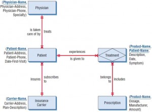
An entity-relationship diagram containing many entities, many different types of relations, and numerous attributes is featured in the figure shown below. In this E-R diagram, we are concerned about a billing system, and in particular with the prescription part of the system. (For simplicity, we assume that office visits are handled differently and are outside the scope of this system.)

The entities are PRESCRIPTION, PHYSICIAN, PATIENT, and INSURANCE CARRIER. The entity TREATMENT is not important for the billing system, but it is part of the E-R diagram because it is used to bridge the gap between PRESCRIPTION and PATIENT. We therefore drew it as an associative entity in the figure.
Here, a PHYSICIAN treats many PATIENT(s) (1:M), who each subscribe to an individual INSURANCE CARRIER. Of course, the PATIENT is only one of many patients that subscribe to that particular INSURANCE CARRIER (M:1).
To complete the PHYSICIAN’s records, the physician needs to keep information about the treatments a PATIENT has. Many PATIENT(s) experience many TREATMENT(s), making it a many-to-many (M:N) relationship. TREATMENT is represented as an associative entity because it is not important in our billing system by itself. TREATMENT(s) can include the taking of PRESCRIPTION( s), and thus is also an M:N relationship, because many treatments may call for combinations of pharmaceuticals and many drugs may work for many treatments.
Some detail is then filled in for the attributes. The attributes are listed next to each of the entities, and the key is underlined. For example, the entity PRESCRIPTION has a PRODUCTNAME, DOSAGE, MANUFACTURER, and AMOUNT. Ideally, it would be beneficial to design a database in this fashion, using entity-relationship diagrams and then filling in the details concerning attributes. This top-down approach is desirable, but it is sometimes very difficult to achieve.
An attribute is some characteristic of an entity. There can be many attributes for each entity. For example, a patient (entity) can have many attributes, such as last name, first name, street address, city, state, and so on. The date of the patient’s last visit as well as the prescription details are also attributes. When the data dictionary was constructed in chapter “Analyzing Systems using Data Dictionaries“, the smallest particular described was called a data element. When files and databases are discussed, these data elements are generally referred to as data items. Data items are in fact the smallest units in a file or database. The term data item is also used interchangeably with the word attribute.
Data items can have values. These values can be of fixed or variable length; they can be alphabetic, numeric, special characters, or alphanumeric. Examples of data items and their values can be found in the table below.
| Entity | Data Item | Value |
|---|---|---|
| Salesperson | Salesperson Number Salesperson Name Company Name Address Sales | 87254 Kaytell Music Unlimited 45 Arpeum Circle $20,765 |
| Package | Width Height Length Weight Mailing Address Return Address | 2 16 16 3 765 Dulcinea Drive P.O. Box 341, Spring Valley, MN |
| Order | Product(s) Description(s) Quantity Ordered Last Name of Customer First Initial Street Address City State Zip Code Credit Card Number Date Order Was Placed Amount Status | B521 “My Fair Lady” compact disc 1 Kiley R. 765 Dulcinea Drive La Mancha CA 93407 65-8798-87 01/03/2010 $6.99 Backordered |
Sometimes a data item is also referred to as a field. A field, however, represents something physical, not logical. Therefore, many data items can be packed into a field; the field can be read and converted to a number of data items. A common example of this is to store the date in a single field as MM/DD/YYYY. To sort the file in order by date, three separate data items are extracted from the field and sorted first by YYYY, then by MM, and finally by DD.
A record is a collection of data items that have something in common with the entity described. Figure below is an illustration of a record with many related data items. The record shown is for an order placed with a mail-order company. The ORDER-#, LAST NAME, INITIAL, STREET ADDRESS, CITY, STATE, and CREDIT CARD are all attributes. Most records are of fixed length, so there is no need to determine the length of the record each time.

Under certain circumstances (for instance, when space is at a premium), variable-length records are used. A variable-length record is used as an alternative to reserving a large amount of space for the longest possible record, such as the maximum number of visits a patient has made to a physician. Each visit would contain many data items that would be part of the patient’s full record (or file folder in a manual system). Later in this chapter, normalization of a relation is discussed. Normalization is a process that eliminates repeating groups found in variable-length records.
A key is one of the data items in a record that is used to identify a record. When a key uniquely identifies a record, it is called a primary key. For example, ORDER-# can be a primary key because only one number is assigned to each customer order. In this way, the primary key identifies the real-world entity (customer order).
Special care must be taken when designing the primary key. Often it is a sequential number or a sequential number with a self-checking number (called a check digit) at the end of the digits. At times there is some meaning built into the primary key, but defining a primary key based on an attribute is considered a risk. If the attribute changes, the primary key will also change, creating a dependency between the primary key and the data.
An example of a primary key based on data is using a state abbreviation for the state name or an airline luggage code for an airport name. An attribute or a collection of attributes that can serve as a primary key is called a candidate key. A primary key should also be minimal and contain no extra attributes than are necessary to identify a record.
A key is called a secondary key if it cannot uniquely identify a record. Secondary keys either may be unique or may identify multiple records in a database. Secondary keys can be used to select a group of records that belong to a set (for example, orders from the state of Virginia).
When it is not possible to identify a record uniquely by using one of the data items found in a record, a key can be constructed by choosing two or more data items and combining them. This key is called a concatenated, or composite, key. When a data item is used as a key in a record, the description is underlined. Therefore, in the ORDER record (ORDER-#, LAST NAME, INITIAL, STREET ADDRESS, CITY, STATE, CREDIT CARD), the key is ORDER-#. If an attribute is a key in another file, it should be underlined with a dashed line.
Some databases allow the developer to use an object identifier (OID), which is a unique key for each record in the database, not just in a table. Given an object identifier, one record will be obtained regardless of the table on which it exists. This may be included with an order or a payment confirmation, along with a message like, “This is your confirmation number.”
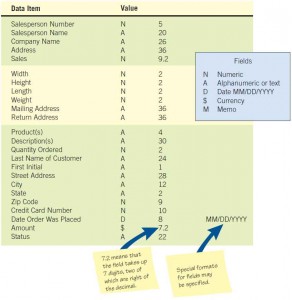
Metadata are data about the data in the file or database. Metadata describe the name given and the length assigned to each data item. Metadata also describe the length and composition of each of the records.
Figure illustrated below is an example of metadata for a database for some generic software. The length of each data item is indicated according to a convention, where 7.2 means that seven spaces are reserved for the number, two of which are to the right of the decimal point. The letter N signifies “numeric,” and the A stands for “alphanumeric.” The D stands for “date” and is automatically in the form MM/DD/YYYY. Some programs, such as Microsoft Access, use plain English for metadata, so words such as text, currency, and number are used. Microsoft Access provides a default of 50 characters as the field length for names, which is fine when working with small systems. If, however, you are working with a large database for a bank or a utility company, for example, you do not want to devote that much space to that field. Otherwise, the database would become quite large and filled with wasted space. That is when you can use metadata to plan ahead and design a more efficient database.

