Normalization is the transformation of complex user views and data stores to a set of smaller, stable data structures. In addition to being simpler and more stable, normalized data structures are more easily maintained than other data structures.
The Three Steps of Normalization
Beginning with either a user view or a data store developed for a data dictionary (see Chapter 8), the analyst normalizes a data structure in three steps, as shown in the figure below. Each step involves an important procedure, one that simplifies the data structure.
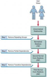
The relation derived from the user view or data store will most likely be unnormalized. The first stage of the process includes removing all repeating groups and identifying the primary key. To do so, the relation needs to be broken up into two or more relations. At this point, the relations may already be of the third normal form, but it is likely more steps will be needed to transform the relations to the third normal form.
The second step ensures that all nonkey attributes are fully dependent on the primary key. All partial dependencies are removed and placed in another relation.
The third step removes any transitive dependencies. A transitive dependency is one in which nonkey attributes are dependent on other nonkey attributes.
A Normalization Example
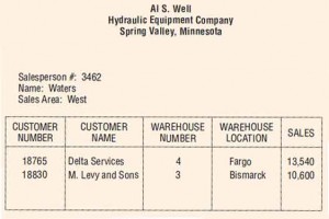
Figure shown below is a user view for the Al S. Well Hydraulic Equipment Company. The report shows the (1) SALESPERSON-NUMBER, (2) SALESPERSON-NAME, and (3) SALES-AREA. The body of the report shows the (4) CUSTOMER-NUMBER and (5) CUSTOMER-NAME. Next is the (6)WAREHOUSE-NUMBER that will service the customer, followed by the (7) WAREHOUSE-LOCATION, which is the city in which the company is located. The final information contained in the user view is the (8) SALES-AMOUNT. The rows (one for each customer) on the user view show that items 4 through 8 form a repeating group.
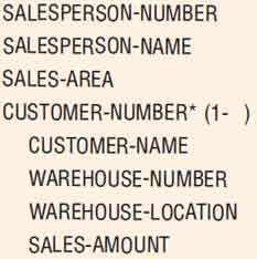
If the analyst was using a data flow/data dictionary approach, the same information in the user view would appear in a data structure. Figure below shows how the data structure would appear at the data dictionary stage of analysis. The repeating group is also indicated in the data structure by an asterisk (*) and indentation.
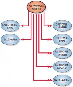
Before proceeding, note the data associations of the data elements in shown in the figure below. This type of illustration is called a bubble diagram or data model diagram. Each entity is enclosed in an ellipse, and arrows are used to show the relationships. Although it is possible to draw these relationships with an E-R diagram, it is sometimes easier to use the simpler bubble diagram to model the data.
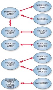
In this example, there is only one SALESPERSON-NUMBER assigned to each SALESPERSON-NAME, and that person will cover only one SALES-AREA, but each SALES-AREA may be assigned to many salespeople: hence, the double arrow notation from SALES-AREA to SALESPERSON-NUMBER. For each SALESPERSON-NUMBER, there may be many CUSTOMER-NUMBER(s).
Furthermore, there would be a one-to-one correspondence between CUSTOMER-NUMBER and CUSTOMER-NAME; the same is true for WAREHOUSE-NUMBER and WAREHOUSE-LOCATION. CUSTOMER-NUMBER will have only one WAREHOUSE-NUMBER and WAREHOUSE-LOCATION, but each WAREHOUSE-NUMBER or WAREHOUSE-LOCATION may service many CUSTOMER-NUMBER(s). Finally, to determine the SALES-AMOUNT for one salesperson’s calls to a particular company, it is necessary to know both the SALESPERSON-NUMBER and the CUSTOMER-NUMBER.
The main objective of the normalization process is to simplify all the complex data items that are often found in user views. For example, if the analyst were to take the user view discussed previously and attempt to make a relational table out of it, the table would look like as shown below. Because this relation is based on our initial user view, we refer to it as SALES-REPORT.
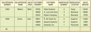
SALES-REPORT is an unnormalized relation, because it has repeating groups. It is also important to observe that a single attribute such as SALESPERSON-NUMBER cannot serve as the key. The reason is clear when one examines the relationships between SALESPERSON-NUMBER and the other attributes in the figure illustration below. Although there is a one-to-one correspondence between SALESPERSON-NUMBER and two attributes (SALESPERSON-NAME and SALES-AREA), there is a one-to-many relationship between SALESPERSON-NUMBER and the other five attributes (CUSTOMER-NUMBER, CUSTOMER-NAME, WAREHOUSE-NUMBER, WAREHOUSE-LOCATION, and SALES-AMOUNT).
SALES-REPORT can be expressed in the following shorthand notation:
SALES REPORT  (SALESPERSON-NUMBER,
        SALESPERSON-NAME, SALES-AREA,
        (CUSTOMER-NUMBER,
        CUSTOMER-NAME,
        WAREHOUSE-NUMBER,
        WAREHOUSE-LOCATION,
        SALES-AMOUNT))
where the inner set of parentheses represents the repeated group.
The first step in normalizing a relation is to remove the repeating groups. In our example, the unnormalized relation SALES-REPORT will be broken into two separate relations. These new relations will be named SALESPERSON and SALESPERSON-CUSTOMER. Figure below shows how the original, unnormalized relation SALES-REPORT is normalized by separating the relation into two new relations. Notice that the relation SALESPERSON contains the primary key SALESPERSON-NUMBER and all the attributes that were not repeating (SALESPERSON-NAME and SALES-AREA).
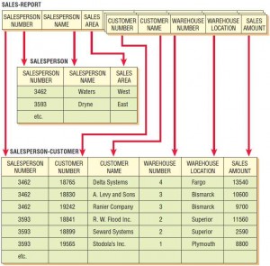
The second relation, SALESPERSON-CUSTOMER, contains the primary key from the relation SALESPERSON (the primary key of SALESPERSON is SALESPERSON-NUMBER), as well as all the attributes that were part of the repeating group (CUSTOMER-NUMBER, CUSTOMER-NAME, WAREHOUSE-NUMBER, WAREHOUSE-LOCATION, and SALES-AMOUNT). Knowing the SALESPERSON-NUMBER, however, does not automatically mean that you will know the CUSTOMER-NAME, SALES-AMOUNT, WAREHOUSE-LOCATION, and so on. In this relation, one must use a concatenated key (both SALESPERSON-NUMBER and CUSTOMER-NUMBER) to access the rest of the information. It is possible to write the relations in shorthand notation as follows:
The relation SALESPERSON-CUSTOMER is a first normal relation, but it is not in its ideal form. Problems arise because some of the attributes are not functionally dependent on the primary key (that is, SALESPERSON-NUMBER, CUSTOMER-NUMBER). In other words, some of the nonkey attributes are dependent only on CUSTOMER NUMBER and not on the concatenated key. The data model diagram in the figure illustration below shows that SALES-AMOUNT is dependent on both SALESPERSON-NUMBER and CUSTOMER-NUMBER, but the other three attributes are dependent only on CUSTOMER-NUMBER.
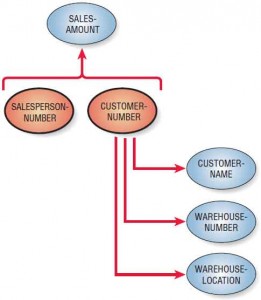
In the second normal form, all the attributes will be functionally dependent on the primary key. Therefore, the next step is to remove all the partially dependent attributes and place them in another relation. Figure below shows how the relation SALESPERSON-CUSTOMER is split into two new relations: SALES and CUSTOMER-WAREHOUSE. These
relations can also be expressed as follows:
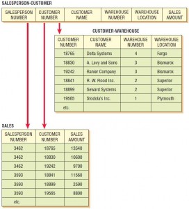
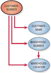
The relation CUSTOMER-WAREHOUSE is in the second normal form. It can still be simplified further because there are additional dependencies in the relation. Some of the nonkey attributes are dependent not only on the primary key, but also on a nonkey attribute. This dependency is referred to as a transitive dependency.
Figure below shows the dependencies in the relation CUSTOMER-WAREHOUSE. For the relation to be a second normal form, all the attributes must be dependent on the primary key CUSTOMER-NUMBER, as shown in the diagram. WAREHOUSE-LOCATION, however, is obviously dependent on WAREHOUSE-NUMBER also. To simplify this relation, another step is required.
A normalized relation is in the third normal form if all the nonkey attributes are fully functionally dependent on the primary key and there are no transitive (nonkey) dependencies. In a manner similar to the previous steps, it is possible to break apart the relation CUSTOMER-WAREHOUSE into two relations, as shown in the figure below.
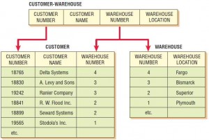
The two new relations are called CUSTOMER and WAREHOUSE, and can be written as follows:
The primary key for the relation CUSTOMER is CUSTOMER-NUMBER, and the primary key for the relation WAREHOUSE is WAREHOUSE-NUMBER.
In addition to these primary keys, we can identify WAREHOUSE-NUMBER to be a foreign key in the relation CUSTOMER. A foreign key is any attribute that is nonkey in one relation but a primary key in another relation. We designated WAREHOUSE-NUMBER as a foreign key in the previous notation and in the figures by underscoring it with a dashed line: __________.
Finally, the original, unnormalized relation SALES-REPORT has been transformed into four 3NF relations. In reviewing the relations shown in the figure below, one can see that the single relation SALES-REPORT was transformed into the following four relations:
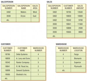
The third normal form is adequate for most database design problems. The simplification gained from transforming an unnormalized relation into a set of 3NF relations is a tremendous benefit when it comes time to insert, delete, and update information in the database.
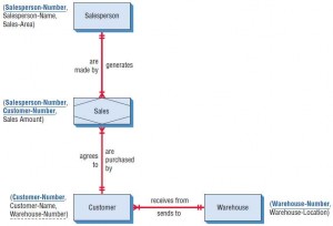
An E-R diagram for the database is shown in the figure below. One SALESPERSON serves many CUSTOMER(s), who generate SALES and receive their items from one WAREHOUSE (the closest WAREHOUSE to their location). Take the time to notice how the entities and attributes relate to the database.
Using the Entity-Relationship Diagram to Determine Record Keys
The E-R diagram may be used to determine the keys required for a record or a database relation. The first step is to construct the E-R diagram and label a unique (primary) key for each data entity. Figure below shows an E-R diagram for a customer order system. There are three data entities: CUSTOMER, with a primary key of CUSTOMER-NUMBER; ORDER, with a primary key of ORDER-NUMBER; and ITEM, with ITEM-NUMBER as the primary key. One CUSTOMER may place many orders, but each ORDER can be placed by one CUSTOMER only, so the relationship is one-to-many. Each ORDER may contain many ITEM(s), and each ITEM may be contained in many ORDER(s), so the ORDER-ITEM relationship is many-to-many.

A foreign key, however, is a data field on a given file that is the primary key of a different master file. For example, a DEPARTMENT-NUMBER indicating a student’s major may exist on the STUDENT MASTER table. DEPARTMENT-NUMBER could also be the unique key for the DEPARTMENT MASTER table.
